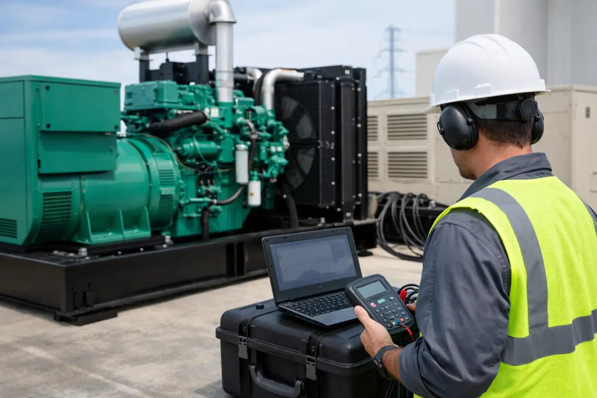
A standby generator that starts but cannot accept its specified load is not a proven resilience asset. This generator load acceptance testing guide sets out how facilities and project teams can verify generating capacity, transfer performance and control response before the site has to depend on them.
Load acceptance testing is particularly relevant at commissioning, following a major installation change, after control-system work, or when a site’s critical load has materially increased. It provides evidence that the generator set, automatic transfer equipment, fuel system and connected distribution can operate as one system under realistic demand.
What generator load acceptance testing proves
A generator load acceptance test confirms that a set can start, stabilise and carry a defined electrical load without exceeding operating limits. For a standby installation, the focus is not simply whether the engine runs. The test must show that the power system transfers critical services correctly, maintains acceptable voltage and frequency, and continues operating for the agreed duration.
The acceptance criteria should be tied to the project specification. This will normally identify the required standby rating, voltage, frequency, permitted transfer time, load steps, run duration and fuel autonomy. If the generator is intended for prime power, the testing regime must also reflect its continuous operating duty and expected load profile.
A well-executed test can expose faults that a routine no-load exercise will not reveal. These include inadequate fuel supply, incorrect governor settings, battery weakness, cooling limitations, loose terminations, unstable voltage regulation and poorly coordinated protection settings. Finding such issues under controlled conditions is materially different from finding them during a mains failure.
Load acceptance testing versus load bank testing
The terms are often used interchangeably, but they are not identical. A load bank test applies a controlled electrical load directly to the generator. It is useful where the building load cannot be interrupted, is unavailable during commissioning, or does not provide enough demand to test the generator properly.
Load acceptance testing may use a load bank, the live site load, or a combination of both. Testing against live load gives the clearest picture of transfer operation and real equipment behaviour, but it carries greater operational risk. Testing with a load bank gives repeatable demand and controlled load steps, but it does not prove that every downstream circuit, automatic transfer switch or essential load will behave correctly.
For many critical sites, the practical approach is staged. The generator is first proven with a suitably sized load bank, then tested through the actual transfer arrangement during an agreed outage window. The right method depends on the site’s risk tolerance, access to a test load and the consequences of an interruption.
Define the duty, rating and test load before testing
Testing should begin with the generator data plate and the design load schedule, not with connecting cables. Confirm the set’s standby and prime power ratings, phase configuration, voltage, frequency, power factor and ambient derating assumptions. A generator rated at a particular kVA under defined conditions may have a lower usable output in high ambient temperatures, at altitude, or where auxiliary equipment has been added.
The relationship between kVA and kW also matters. Generator capacity is often stated in kVA, while the site’s load schedule is expressed in kW. At a power factor of 0.8, a 500 kVA generator provides 400 kW. Poor power factor, harmonic distortion and the starting current of motors can alter what the set can support in practice.
Identify the largest anticipated load step. A chilled-water plant, large pump, compressor or lift group can impose a far more severe transient than its normal running load suggests. Where possible, sequence large loads to avoid unnecessary frequency dip and voltage disturbance. The acceptance plan should reflect the real operating sequence, rather than an idealised total load figure.
Prepare the site and test documentation
An acceptance test should be controlled by a written method statement and risk assessment. The person leading the test needs authority to stop it if readings become unsafe or site conditions change. Where live loads are involved, facilities operations, electrical contractors, generator engineers and affected occupiers should understand the switching plan and communications route.
Before the test, inspect the installation. Check fuel quantity and fuel condition, engine oil, coolant, belts, hoses, battery charger operation, exhaust condition, ventilation paths and enclosure access. On a silent generator, confirm that inlet and discharge air routes are unobstructed. On an open generator installation, ensure the plantroom ventilation design can remove radiator heat at the planned load.
Review the electrical side as carefully as the engine. Verify earthing arrangements, cable ratings, breaker settings, phase rotation, remote emergency-stop circuits, alarms, automatic transfer switch settings and generator controller configuration. Confirm that the load bank is rated for the voltage, phase arrangement and duration required, with adequate connection cables and ventilation.
The test record should include ambient conditions, starting battery voltage, engine operating readings, voltage, frequency, current by phase, kW, kVA, power factor, fuel level, alarm events and transfer times. A record without time-stamped measurements offers limited value when a fault later needs to be investigated.
Carry out the generator load acceptance test in stages
Start the generator in accordance with the manufacturer’s procedure and allow it to reach stable operating temperature before applying significant load. Confirm that no active alarm, leak, abnormal vibration or exhaust issue is present. Initial readings at no load establish a useful baseline, but they are not an acceptance result.
Apply load progressively. The exact increments should follow the project specification and the expected site profile. A common approach is to introduce measured steps, allowing the engine and alternator to stabilise at each point while recording voltage, frequency, oil pressure, coolant temperature and phase balance. The team should observe both the immediate transient response and the stable condition after the load settles.
At the agreed test load, hold the generator for the specified duration. This is where cooling capacity, fuel delivery and electrical connections are properly challenged. Watch for rising coolant temperature, declining oil pressure, unstable frequency, uneven phase currents, smoke, fuel leaks or nuisance alarms. Do not dismiss an intermittent alarm simply because the set continues to run.
Where the test includes automatic transfer, simulate a normal mains failure through the approved switching procedure. Record the generator start signal, start time, availability time and transfer completion. Confirm that priority loads are restored in the correct order and that non-essential loads remain shed where designed. On restoration of the mains, verify retransfer delays, generator cool-down and return to automatic readiness.
The final stages should include a controlled load reduction and shutdown. A generator should not be stopped immediately after carrying heavy load unless there is an emergency. Allow the configured cool-down cycle to operate, then inspect the set again for fluid loss, loose connections, abnormal heat and fault messages.
Common acceptance failures and what they indicate
Low frequency under a load step can indicate governor response issues, excessive load application, fuel restriction or an engine output problem. Low voltage may point to AVR settings, sensing faults, alternator issues or an unsuitable reactive load profile. A repeated breaker trip requires investigation of protection coordination and fault level assumptions, not a larger breaker fitted as a quick fix.
High coolant temperature is frequently an installation issue rather than an engine defect. Restricted ventilation, recirculation of hot discharge air, undersized louvres or a contaminated radiator can all prevent a correctly specified generator from delivering its rating. Similarly, a set that runs well for a short test may fail during a longer run because the fuel return, day tank or bulk tank arrangement is inadequate.
Uneven current across phases should be assessed against the alternator manufacturer’s permitted imbalance. Severe imbalance can overheat windings even when total kVA appears acceptable. Sites with variable-speed drives, UPS systems and other non-linear loads may also need harmonic assessment, particularly where the generator is expected to support sensitive electronic equipment.
Turn test results into an operational decision
The test report should state whether the installation passed the agreed criteria, identify any deviations and assign clear corrective actions. If the test was limited by an unavailable site load or reduced load bank capacity, say so plainly. A partial test is useful evidence, but it is not proof of full rated performance.
For new or replacement equipment, retain the acceptance report with the operation and maintenance records. It establishes a baseline for future servicing and helps distinguish a developing fault from normal performance. Global Generators can support specification discussions where generator rating, enclosure format and application duty need to be aligned before commissioning begins.
A generator is only as dependable as the system around it. Treat load acceptance testing as the point at which the site proves its recovery plan under controlled conditions, then use the findings to remove uncertainty while there is still time to act.