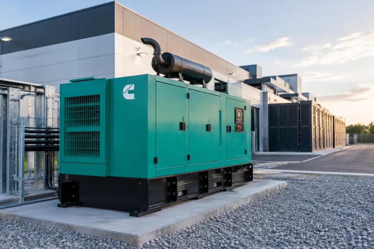
A data centre generator example is most useful when it starts with the actual consequence of a power loss. For a facility supporting critical IT, communications and cooling, the generator is not simply a large diesel set on standby. It is one part of a coordinated power system that must carry defined loads, start promptly, accept load in the correct sequence and operate for the required outage duration.
The example below shows how a facilities team might specify standby generation for a medium-sized data centre. The figures are illustrative, but the approach applies whether the requirement is for a single 250 kVA set supporting an edge facility or multiple synchronised generators protecting a larger site.
A data centre generator example: 800 kW critical load
Assume a data centre has an assessed critical load of 800 kW during a mains failure. That figure includes 600 kW of IT demand, 130 kW of cooling and ventilation essential to maintain operating conditions, and 70 kW for UPS losses, lighting, security, fire systems, pumps and controls.
The site has a 400/230 V, 50 Hz, three-phase incoming supply. Its UPS systems hold the IT load during the short interval between utility failure and generator stabilisation. The generator plant is required to support the building for a planned 24-hour outage without refuelling, while allowing for operational growth.
A suitable starting configuration could be two 1,250 kVA diesel generators operating in parallel. At a power factor of 0.8, each set has a 1,000 kW standby capacity. With one generator unavailable for maintenance or fault investigation, the remaining set can still carry the 800 kW critical load at 80% of its available standby output.
That arrangement provides N+1 resilience at generator level. It does not automatically make the whole electrical system N+1. The switchgear, fuel transfer equipment, control panels, bus sections, outgoing feeders and cooling distribution must also be assessed for single points of failure. A generator package is only as dependable as the systems that enable it to start, connect and deliver power.
Start with load, not the generator rating
Selecting a set purely because its kVA rating looks larger than the estimated site demand is a common and costly mistake. The required rating depends on the real load profile, power factor, motor starting behaviour, UPS characteristics, future expansion and the duty classification.
For the example site, 800 kW at a nominal 0.8 power factor equates to 1,000 kVA. If the design called for one generator only, a 1,000 kVA set would leave no practical capacity margin and no resilience. It would also be vulnerable to site derating and transient load conditions. The two-set 1,250 kVA arrangement provides both headroom and redundancy, provided each unit is specified at the required standby rating.
Standby power and prime power ratings must not be treated as interchangeable. A standby-rated generator is intended for emergency operation during utility failure, subject to the manufacturer’s operating limits. A prime-rated set is designed for variable load over extended hours where mains power is unavailable or unsuitable. A data centre with reliable utility supply normally specifies standby duty, while a remote or permanently off-grid facility may need a prime power design.
Ambient conditions matter as well. High air temperature, altitude, restricted airflow and poor plant-room ventilation can reduce available output. A generator rated at 1,250 kVA under standard conditions may require derating at the installation location. This should be confirmed before procurement, not after the enclosure has arrived on site.
Allow for step loading and UPS operation
Data centre loads do not always connect as one predictable block. The UPS will support the IT estate while the generator starts, reaches stable voltage and frequency, and receives a signal to close onto the emergency bus. Cooling equipment, pumps and other motor loads may then be introduced in stages.
The control philosophy should define the sequence. IT and essential controls are generally prioritised. Large chillers, compressor-based cooling or pump groups may require delayed starts, variable-speed drives or staged connection to prevent a sudden demand from pulling generator voltage and frequency outside acceptable limits.
UPS rectifiers can also introduce non-linear loads and harmonic content. Alternator selection, voltage regulation and generator sizing should account for the particular UPS equipment installed. A site with modern high-efficiency UPS modules may behave very differently from one with older equipment, even where the nameplate kW demand appears similar.
For this reason, the generator supplier needs more than a total site load figure. A useful technical brief includes the critical and non-critical load schedules, UPS make and model, motor sizes, starting method, expected load steps, power factor and proposed future load. This enables the set, alternator and controls to be matched to the operating duty rather than selected on headline kVA alone.
Redundancy must extend beyond the engines
Two generators provide little protection if both rely on a single fuel pump, a common control failure or one unmaintained automatic transfer system. The practical level of resilience should match the site’s uptime commitment and the cost of an outage.
In the 800 kW example, each generator would have its own engine controls, starting batteries, charger and local fuel connections. The paralleling switchboard would be designed so that either set can start automatically, synchronise where required and support the emergency bus. If a generator fails to start, the second unit must receive a prompt start command without manual intervention.
A closed-transition or open-transition transfer approach should be selected around the site’s utility agreement, protection settings and operational requirements. Open-transition transfer creates a short break before reconnecting to an alternative source. The UPS bridges this interruption for protected IT loads. Closed-transition arrangements can reduce transfer disturbance but are more complex and need careful engineering and utility approval where applicable.
Physical arrangement is relevant too. An open generator set may suit a secure internal plant room with correctly designed ventilation, exhaust routing and acoustic treatment. A weatherproof silent generator is often better suited to external installation where noise limits, weather protection and rapid deployment are priorities. Neither format is universally better. The decision depends on the site, access route, acoustic survey, security provisions and maintenance space.
Fuel autonomy is a calculated requirement
A 24-hour runtime target cannot be met by specifying a tank size from a brochure. Fuel consumption varies with generator load, so the calculation should use the anticipated duty point, not an optimistic low-load figure.
If each 1,250 kVA generator is expected to carry the full 800 kW load during an N+1 event, the selected unit’s manufacturer fuel-consumption data at approximately 80% load should be used. The resulting hourly figure is multiplied by the target runtime, then adjusted for usable tank volume, reserve requirements and any planned fuel polishing or transfer arrangements.
For longer outages, a bulk fuel tank with duty and standby transfer pumps may be appropriate. Fuel quality requires the same attention as electrical capacity. Water ingress, microbial contamination and sediment can turn a well-specified generator into a no-start risk. Regular sampling, filtration and fuel polishing should form part of the maintenance regime, particularly where diesel is stored for extended periods.
Testing proves the design
Weekly no-load exercise confirms that an engine can start. It does not prove that the generator can accept the data centre load, that the UPS responds correctly, or that cooling stages reconnect as intended. Meaningful testing includes loaded runs, transfer testing, alarm verification and periodic site-level simulations.
Load-bank testing is valuable where operating a live facility at high generator load is impractical. It allows the engine, alternator and fuel system to be exercised under controlled demand. However, it should complement rather than replace integrated testing of the actual switchgear, UPS, controls and critical distribution.
Records should show start time, stabilisation time, voltage and frequency performance, load acceptance, fuel use, alarm events and corrective actions. Facilities teams should also confirm that remote monitoring reaches the people responsible for responding. An alarm with no escalation route is not a resilience measure.
For buyers evaluating a new installation, the most productive next step is to turn the single-line diagram and load schedule into a generator brief. Global Generators can then match the required standby or prime rating, Cummins-powered engine option, enclosure type and control arrangement to the site’s operating risk.
The right generator is not the largest set that fits the compound. It is the set that has been specified to start, carry the required load, support planned growth and remain serviceable when the mains supply does not return on schedule.