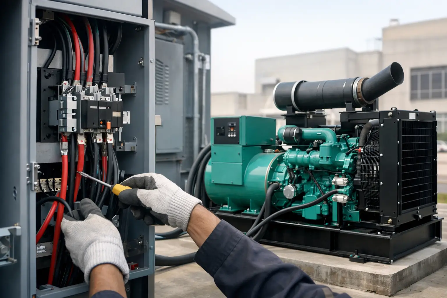
A generator is only useful to a critical site if its power reaches the required loads at the right time. Generator ATS installation is the point where the standby set, mains incomer and distribution system become one controlled power continuity arrangement. Poorly specified switching can leave essential circuits unprotected, introduce unsafe backfeed risk or create a transfer delay that the operation cannot accept.
For facilities managers, contractors and project engineers, the automatic transfer switch is not an accessory. It is a primary item of electrical infrastructure. The installation must reflect the generator duty, load profile, site earthing arrangement and the consequences of a failed transfer.
Start with the critical-load strategy
The first decision is not the ATS make or enclosure size. It is which loads the system is expected to carry during a mains failure. A whole-site transfer may be appropriate for a small commercial premises with a correctly sized standby generator. On a manufacturing plant, hospital, warehouse or telecoms installation, it is often more practical to transfer only essential distribution boards.
Segregating critical loads prevents the generator from being overloaded by non-essential plant. Heating, process machinery, lifts, charging systems and large motor loads can consume capacity quickly, particularly where several items attempt to restart together. A generator rating based only on normal running load can be misleading if the ATS closes onto a high inrush demand.
Define the operational sequence before equipment is ordered. This should confirm the essential circuits, the maximum simultaneous demand, starting currents, permitted transfer interruption and whether load shedding is required. It should also establish whether the generator is standby-only or expected to support prime power operation. These are different duties and should not be treated as interchangeable.
Selecting the ATS for the generator and site supply
An ATS must be rated for more than the headline kVA of the generator. Its current rating needs to accommodate the generator output at the selected voltage and power factor, while allowing for the site’s likely load and any reasonable future expansion. The short-circuit withstand rating also matters. The switchboard fault level at the installation point may exceed what appears necessary from the generator size alone.
For most UK commercial and industrial applications, the ATS will sit between the mains supply and generator supply, feeding a defined essential-load board. The arrangement must prevent parallel connection unless a synchronising and paralleling system has been specifically engineered for that purpose. A conventional transfer switch is designed to break one source before making the other.
The switching poles require particular attention. Three-pole and four-pole ATS arrangements are not directly interchangeable. The correct choice depends on the distribution system and neutral-earthing design, including whether the generator neutral is bonded to earth and whether the mains and generator supplies need their neutrals isolated during transfer. This should be assessed by a competent electrical designer, not selected on price or panel availability.
Open transition, closed transition and bypass options
Open-transition transfer is the usual choice for standby generator systems. The mains source is disconnected, the generator supply is connected and the essential load experiences a brief interruption. For many facilities, that interruption is acceptable where UPS systems protect sensitive IT and control loads.
Closed-transition switching can reduce or remove the break in supply by briefly operating the sources in parallel. It requires appropriate protection, controls and, in many cases, agreement with the distribution network operator. It is not a standard upgrade for every site. The additional engineering is justified only where the business case supports it.
For high-availability facilities, a bypass-isolation ATS can be worthwhile. It enables the transfer equipment to be maintained or replaced while power is routed through a separate manual bypass path. This adds cost and panel space, but it avoids making the ATS itself a single point of failure during maintenance.
Generator ATS installation: location and cable routing
The physical layout influences reliability as much as the component specification. The ATS should be accessible for inspection, functional testing and emergency operation, while protected from water ingress, vibration, excessive heat and accidental impact. An outdoor generator does not automatically mean the switching equipment belongs outdoors. In many projects, a suitably rated indoor ATS panel adjacent to the essential distribution board gives better access and protection.
Cable routes must be designed around voltage drop, installation method, fault protection and the full load current of both supplies. Generator output cables, mains cables and control wiring should be identified clearly and terminated to a documented schedule. Control cables need suitable segregation from power circuits to reduce electrical interference and to make fault-finding simpler.
The generator controller and ATS must exchange the correct start, run and fault signals. At a minimum, the ATS should command generator start on a confirmed mains failure, wait for acceptable generator voltage and frequency, transfer the load, then return to mains only after the restored utility supply has proved stable for the configured time delay. It should subsequently run the generator off-load for a cool-down period before shutdown.
Do not assume factory defaults suit the site. A short mains-failure delay may be appropriate where transfer must occur quickly, but it can create unnecessary starts during brief voltage disturbances. Conversely, an extended delay may be unacceptable for a critical process. Return-to-mains delays need similar thought, particularly on sites with unstable incoming supplies.
Protection, earthing and interlocking cannot be left to commissioning
A correctly installed ATS has to work within the complete protection scheme. Breaker settings, cable ratings, earth-fault arrangements and discrimination with upstream and downstream protective devices should be reviewed as part of the design. Generator fault current is typically much lower than utility fault current, which can affect how quickly conventional protective devices operate when the set is supplying the load.
Mechanical and electrical interlocking must make an unintended connection of the mains and generator sources impossible. Labels should state the source, isolation point and emergency switching procedure in terms that a trained operative can act on under pressure. Clear labelling is a safety control, not a finishing detail.
The generator installation also needs adequate fuel provision, ventilation, exhaust routing, battery charging and access for planned service work. An ATS will transfer perfectly, but the system still fails if the generator cannot start, cannot reject heat or runs out of usable fuel. The electrical changeover and generating set should be commissioned as a single system.
Commissioning tests that prove the changeover works
Commissioning should go beyond observing the generator start from its local controller. The test must simulate the actual loss of mains supply at the ATS and verify the complete operating sequence. This includes correct source isolation, generator start signal, voltage and frequency acceptance, transfer to generator, return transfer and cool-down shutdown.
Record the transfer timings, generator operating values and any alarms observed during the test. Where practical, test with representative load connected. A no-load test cannot show whether the generator maintains voltage during motor starts, whether the ATS handles the intended current, or whether essential equipment restarts in the correct order.
Particular checks should include the following:
- confirmation that no generator supply can backfeed the utility network;
- phase rotation and voltage checks at every affected distribution point;
- verification of remote alarms, generator fault indication and emergency stop interfaces;
- operation of load-shedding controls where fitted; and
- confirmation that maintenance bypass arrangements are labelled and understood.
A documented test result gives the site a baseline for future periodic testing. It also provides useful evidence for insurers, compliance records and internal resilience planning.
Plan for maintenance, not just the first failure
The ATS contains switching mechanisms, sensing components, terminals and control connections that require inspection. Thermal scanning under load, terminal-torque checks, cleaning, functional exercise and battery-condition checks all help prevent a dormant fault becoming visible only during an outage.
Generator testing should reflect the real duty. Regular unloaded exercise confirms that the engine starts, but periodic on-load testing is more meaningful for critical installations. It identifies issues with fuel delivery, cooling, load acceptance and control stability that may not appear during a short no-load run.
Where a site has expanded since the original installation, reassess the essential-load schedule. Additional servers, refrigeration, pumps or process equipment can quietly erode generator capacity. A transfer switch may still operate exactly as designed while the generator becomes unable to carry the demand placed upon it.
Global Generators can support specification discussions across standby and prime-rated diesel generator sets, including silent and open configurations from smaller commercial units to large industrial capacities. The right set should be matched to the ATS arrangement, not selected as an isolated kVA figure.
A dependable changeover scheme is built before the mains fails: identify the loads that matter, engineer the switching and earthing correctly, and prove the sequence under realistic conditions. That preparation gives operators a controlled response when normal supply is no longer available.