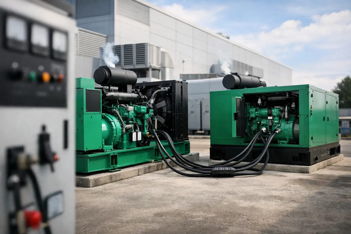
A single generator can cover many standby duties, but it also creates a single point of failure. Where a site cannot accept that risk, this generator paralleling guide sets out the decisions behind a multi-set system: capacity, load steps, switchgear, controls and testing. The objective is not simply to run generators together. It is to maintain stable, controlled power when utility supply is lost, when demand changes, or when one set is unavailable.
What generator paralleling achieves
Generator paralleling connects two or more generating sets to a common busbar so they share the site load. Depending on the design, the sets may operate together in island mode, with no utility supply present, or in parallel with the mains. A properly specified system can provide N+1 resilience, support larger loads than a single set can economically supply, and allow maintenance without taking the entire standby plant out of service.
For a hospital, data facility, telecoms installation, utility asset or continuous manufacturing process, this arrangement changes the failure model. If one generator is isolated for servicing or trips on a genuine fault, the remaining available sets can continue carrying essential demand, provided the system has adequate spare capacity. That is the practical value of paralleling: planned maintenance and individual equipment faults no longer have to mean a full loss of backup power.
It is not automatically the right answer for every site. Paralleling introduces additional controls, protection, engineering and commissioning requirements. For a modest, non-critical load with a straightforward changeover arrangement, one correctly sized generator may be the more dependable and cost-effective choice. The case for multiple sets strengthens when uptime, future expansion, large load size or maintenance access materially affect operations.
The generator paralleling guide: start with the load
The correct starting point is a load study, not the combined kVA shown on a proposed generator schedule. Establish the actual demand, the essential load, the largest motor or transformer step, the power factor and the expected operating profile. Standby operation after a utility failure has different requirements from prime power operation at a remote site or construction project.
A generator system must handle both steady-state demand and transient events. Motor starting, lift equipment, pumps, refrigeration compressors, UPS rectifiers and large variable-speed drives can create a rapid change in kW and kVAr demand. If that step exceeds the available transient capability, frequency and voltage can dip enough to affect sensitive equipment or trigger protection.
Consider a site with a 1,200 kVA essential load. Two 1,000 kVA sets may appear sufficient on paper, but the result depends on the required rating, environmental derating, starting sequence and redundancy target. If N+1 resilience is required, one set must be capable of carrying the agreed essential load after another set is unavailable. Three appropriately rated generators may therefore be more suitable than two, even though the headline total capacity is higher than the normal demand.
Load sequencing is often the most economical way to control the problem. Rather than energising all plant at once after an outage, the control system can restore life safety, communications, controls and critical process loads first, then add less critical circuits in planned stages. This reduces the largest step imposed on the generators and can avoid oversizing the entire installation.
Standby, prime and continuous duty
The rating basis must be explicit. Standby power is intended for emergency use during utility failure, subject to the manufacturer’s applicable operating limits. Prime power is intended for variable-load applications where the generator may be the main supply. A system selected for standby duty should not be assumed suitable for extended prime operation simply because the kVA figure appears adequate.
This distinction also affects fuel autonomy, servicing intervals, emissions arrangements and the commercial evaluation of the package. Procurement documents should state the anticipated annual operating hours, load profile, site altitude, ambient temperature and any requirement to run in parallel with the utility.
Synchronisation, load sharing and protection
Before a generator closes onto a live busbar, its voltage, frequency and phase angle must be matched to that bus. This is synchronisation. Paralleling controls monitor these conditions and command the generator breaker to close within acceptable limits. Closing out of synchronism can impose severe mechanical and electrical stress on the alternator, engine coupling, breaker and connected system.
Once connected, the generators must share load in a stable manner. Active power, measured in kW, is generally shared through engine governor control. Reactive power, measured in kVAr, is shared through alternator voltage regulator control. Modern digital controls can manage this automatically, but their settings, communications and operating modes still require careful engineering. A system that shares kW accurately but circulates reactive current between sets is not operating correctly.
The switchgear is as important as the generators. A typical arrangement includes generator circuit breakers, a common synchronising bus, protective relays, metering, control panels and an automatic mains failure interface. Larger or more complex installations may include sectionalised busbars, bus couplers, feeder protection, remote monitoring and integration with the building management system.
Protection coordination needs to be assessed across the whole electrical installation. The generator system must detect faults quickly enough to protect equipment, yet discriminate with downstream devices so a local fault does not unnecessarily remove the complete essential supply. Relevant functions may include overcurrent, earth fault, reverse power, under- and over-voltage, under- and over-frequency, loss of excitation, vector shift and synch-check protection. The exact scheme depends on the supply arrangement, earthing method and whether utility paralleling is permitted.
Utility paralleling requires additional control
Parallel operation with the mains is not the same as generator-to-generator paralleling. It can be used for closed-transition transfer, peak shaving, export control, load testing or improved continuity during a transfer. However, it requires agreement with the network operator and a clear protection philosophy to prevent unintended backfeed or unstable operation.
For many critical standby sites, a brief overlap during transfer may be valuable because it avoids a break before the load is accepted by the generators. Yet this benefit must be weighed against the added switchgear and compliance requirements. Do not treat a mains-parallel option as a standard add-on. Define its operational purpose first.
Select generators as a matched power system
Matched generator sets simplify control integration and load-sharing performance. Ideally, units in the same paralleling group should have compatible engine-governor characteristics, alternator regulation, control platforms, voltage and frequency ratings, and protection interfaces. Identical sets are often the simplest route, particularly where the system relies on a common spare-parts strategy.
Mixed sets can be paralleled, but they need more detailed review. A smaller generator may reach its load limit before the larger units, and differences in transient response can make sharing less predictable. Where a phased expansion is planned, specify the initial controls, busbar rating and physical switchgear space for the final configuration rather than treating future generators as an afterthought.
Enclosure type also matters. Silent generators are generally appropriate where noise control, weather protection and accessible external installation are priorities. Open generators may suit plantrooms with purpose-designed ventilation, fire protection and acoustic treatment. Neither option is inherently better; the site environment, maintenance access and required attenuation level should decide the configuration.
Fuel is part of resilience, not a separate detail. Calculate usable fuel capacity against the expected load and required runtime, allowing for generator consumption variation, tank reserve, fuel polishing arrangements and refuelling access during an incident. For a multi-set plant, the fuel system must maintain reliable supply to every running engine without creating a common failure point in transfer pumps, controls or pipework.
Commissioning proves the design
A parallel generator installation should not be accepted solely on the basis that each individual set starts. Commissioning must demonstrate the whole operating sequence under realistic conditions. This includes utility failure simulation, automatic start, synchronisation, breaker operation, load acceptance, staged restoration, load shedding, generator failure response and return-to-mains procedures.
Load-bank testing is valuable, particularly where the site load cannot safely provide enough demand to verify system capacity. It allows engineers to test each generator, the common bus and the load-sharing controls at meaningful load levels. Where possible, tests should also confirm response to a sudden load step and the ability to carry the essential load with the largest generator unavailable.
Document the final settings, single-line diagrams, cause-and-effect logic, operating procedures and maintenance requirements. The people responsible for the site need to understand what the system will do automatically, what alarms demand intervention and how to isolate equipment safely. A sophisticated control panel does not remove the need for disciplined operational procedures.
Maintaining a parallel standby plant
Routine exercise should reflect the system’s real purpose. Running each generator independently confirms basic starting performance, but it does not prove synchronisation, load sharing or common-bus operation. Planned parallel tests should be included in the maintenance regime, with records reviewed for unequal loading, abnormal temperatures, battery condition, fuel issues and recurring alarms.
Maintenance planning is one of the strongest reasons to install N+1 capacity, but only if it is used properly. Isolate and service one set at a time while confirming the remaining plant can support the agreed critical load. Keep control software, relay settings and panel backups under change control. An undocumented adjustment to protection or governor parameters can compromise a system that previously performed correctly.
For projects where availability is non-negotiable, Global Generators can help define generator ratings, enclosure options and a practical configuration for a parallel power plant. The most reliable arrangement is the one designed around the real load, the required failure tolerance and a commissioning plan that proves performance before the first outage does.