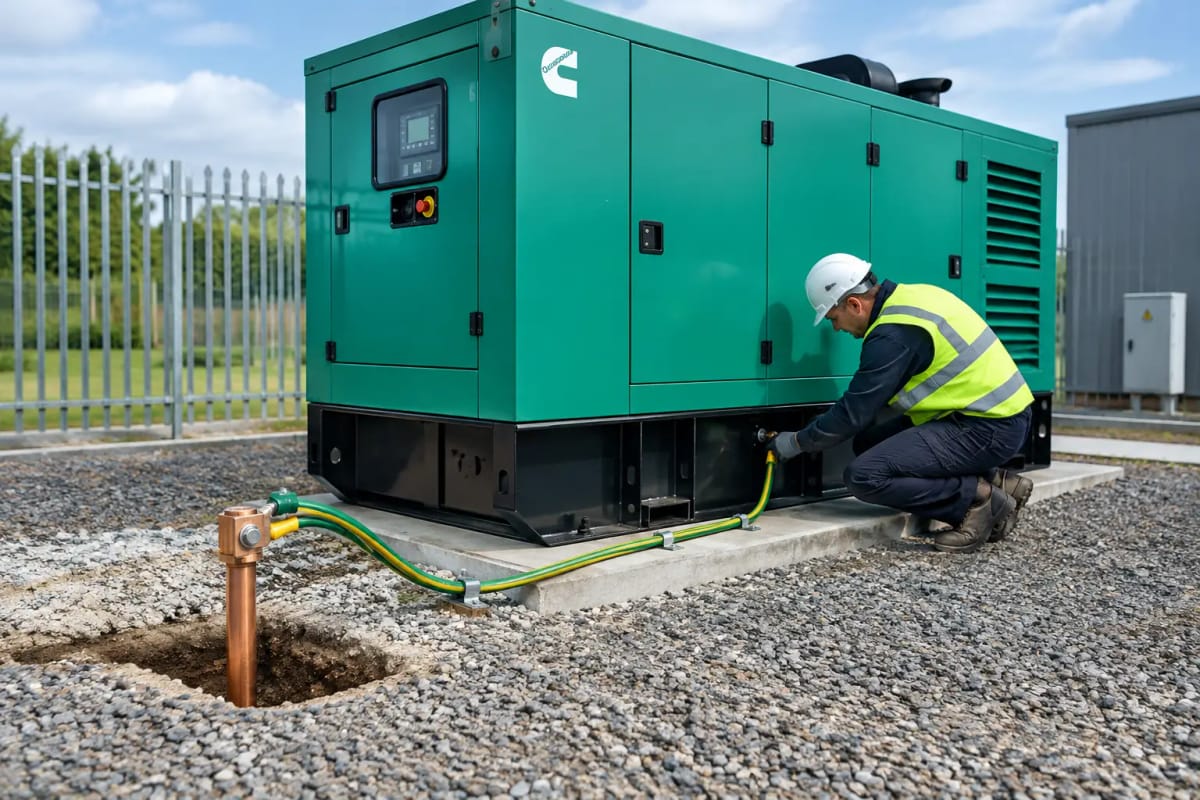
A generator can start, carry its rated load and still leave a site exposed if its earthing arrangement is wrong. This generator earthing requirements guide explains the decisions that must be resolved before a standby or prime power set is connected. For facilities teams, contractors and project engineers, the objective is clear: ensure faults disconnect safely, protective devices operate as intended and transfer between utility and generator supply does not create an unsafe neutral or earth path.
Earthing is not an accessory to generator procurement. It is part of the electrical system design. The required arrangement depends on the incoming supply, generator neutral configuration, automatic transfer switch design, distribution layout, operating duty and whether the set will run independently or in parallel with another source.
Generator earthing requirements: start with the system
The generator frame, enclosure, control panel and exposed conductive parts must be connected to the installation’s protective earthing system. This protective bonding limits dangerous touch voltages if an insulation fault develops inside the alternator, cabling or connected distribution equipment.
That is only one part of the design. The critical engineering question is how the generator neutral is treated when the generator is supplying the installation. A protective earth conductor, an earth electrode and a neutral-to-earth connection perform different functions. Treating them as interchangeable can prevent fault protection from operating correctly.
A competent electrical designer should establish whether the generator operates as a separately derived source. In simple terms, this depends largely on whether the neutral is switched at transfer. That decision determines where, and whether, the generator neutral is bonded to earth.
The installation must also be assessed against the applicable edition of BS 7671, the Electricity at Work Regulations 1989, distributor requirements and any site-specific rules. Healthcare, data, utilities, construction and hazardous environments may impose further design and verification requirements.
The transfer switch determines the neutral arrangement
The changeover equipment is central to safe generator earthing. Its pole configuration needs to be specified early, not selected after the generator has arrived on site.
Three-pole transfer switching
A three-pole automatic transfer switch switches the live conductors but leaves the neutral connected. In many installations, the generator neutral remains referenced through the existing supply earthing arrangement. A separate generator neutral-to-earth bond may create parallel neutral-earth paths, circulating current and unreliable protective-device operation.
This arrangement can be suitable, but only when the wider system has been designed for it. It requires particular care on TN-C-S or PME supplies, where the distributor’s conditions and the nature of the generator connection matter. Do not assume that a generator earth rod alone makes a PME-connected installation suitable for every operating condition.
Four-pole transfer switching
A four-pole transfer switch switches the neutral as well as the live conductors. When the generator is running, it is normally treated as a separately derived source. In that state, the generator neutral requires a deliberate reference to earth, usually through a correctly positioned neutral-to-earth bond as part of the designed arrangement.
The bond must be in one defined location. Multiple neutral-earth bonds can introduce circulating current and complicate fault finding. No bond at all may leave the generator supply without a reliable fault-current path. The correct location can be within the generator control system, the transfer equipment or the distribution arrangement, depending on the approved design and generator manufacturer’s documentation.
Manual changeover and temporary connections
Manual switches and temporary generator connection panels need the same level of scrutiny. They are often used during maintenance, construction works or emergency deployment, when rushed connections increase risk. The switching sequence, neutral treatment, protective conductor continuity and generator output protection should be documented clearly at the connection point.
Earth electrodes are not a universal answer
A dedicated earth electrode may form part of the generator earthing system, particularly at isolated sites, temporary installations or locations where the generator supplies a separately derived system. However, specifying an earth rod without assessing the complete fault-protection strategy is not enough.
Electrode performance varies with soil type, moisture, temperature, installation depth and seasonal conditions. A low earth electrode resistance reading is useful, but it does not by itself prove that circuit protective devices will disconnect within the required time. The design must consider the fault loop impedance, generator alternator characteristics, cable length, protective-device settings and available fault current.
Generator fault current is often lower than the fault current available from the public network. This is especially relevant on larger distribution systems with long submains. A breaker that clears a utility-supplied fault quickly may not operate at the required speed when supplied by an alternator. Protective coordination must therefore be checked in generator mode, not only under normal mains operation.
For mobile generators, construction compounds and agricultural or remote sites, the installation may need an earth electrode arrangement designed around local conditions and the intended distribution system. RCD selection, discrimination and testing become particularly important where socket outlets, hand-held tools or temporary cables are used.
Specify the generator and protection as one package
The generator set should be selected with the electrical design in mind. Rated kVA is essential, but it does not answer the earthing question on its own. The alternator winding configuration, available short-circuit current, neutral accessibility, control-panel protection and intended connection method all affect the final arrangement.
A standby generator feeding a building through an automatic transfer switch has different requirements from a prime power set supporting a remote processing plant. Likewise, a silent generator housed outdoors may need consideration of external earthing connections, corrosion protection and cable gland integrity, while an open generator installed in a plantroom needs a coordinated connection to the site main earthing terminal.
The following information should be agreed before procurement and installation:
- Incoming supply earthing type and main earthing arrangement.
- Transfer switch pole configuration and switching sequence.
- Generator neutral arrangement and designated neutral-to-earth bond location.
- Protective-device ratings, settings and discrimination in both mains and generator operation.
- Earth electrode design where required, including test access and corrosion-resistant connections.
- Cable sizes, protective conductor sizes, fault-loop performance and distribution distances.
This information allows the generator supplier, electrical contractor and consulting engineer to work from the same basis. It also avoids a common late-stage problem: a correctly sized generator that cannot be safely commissioned because the changeover and earthing design were not coordinated.
Installation details that affect long-term reliability
Earthing connections need to remain effective for the life of the equipment, not just at commissioning. Use suitably rated conductors, correctly terminated lugs and protected routes. Connections exposed to weather, vibration, fuel contamination or corrosive atmospheres require particular attention. Generator vibration can loosen poorly secured terminals over time, while external earth tape and clamps can deteriorate unnoticed.
The generator frame should be bonded to the site earthing system using the designated connection point. Metallic fuel systems, cable containment and ancillary plant may also require bonding in accordance with the installation design. Do not use fuel pipework, structural steelwork or a casual connection to nearby metalwork as a substitute for a designed protective earth path.
Where a generator is supplied with an integrated control panel, confirm the manufacturer’s terminal markings and internal neutral-earth link status before connection. Sets can be supplied for different markets and applications, and assumptions based on a previous installation are not a safe basis for commissioning.
Testing and commissioning before handover
Generator earthing should be verified as part of formal electrical commissioning. Visual inspection comes first: confirm conductor routes, terminations, bonding points, transfer switch connections, labels and the position of any neutral-earth bond.
Testing should then demonstrate continuity of protective conductors, earth electrode performance where fitted, polarity, insulation resistance where appropriate, earth fault loop impedance and RCD operation. Functional tests must cover both utility and generator modes. The generator should be run under a representative load where practical, with protection behaviour and transfer operation observed.
For critical facilities, record the final earthing schematic, protection settings, test results and operating sequence in the site handover pack. These records are valuable during future generator replacement, switchgear upgrades and fault investigations. They also give maintenance teams a clear reference when periodic testing is due.
Avoid the common design failures
The most frequent failures are avoidable: fitting a neutral-earth bond without confirming transfer-switch operation, relying on an earth rod without verifying fault disconnection, or checking protective devices only against utility fault levels. Another is allowing separate contractors to supply the generator, ATS and distribution equipment without one party owning the final earthing design.
For higher-risk sites, appoint a competent electrical designer to issue a single-line diagram and earthing philosophy before installation begins. This is especially worthwhile where the generator supports life safety systems, production-critical loads, telecoms equipment or a large multi-board distribution network.
Global Generators can support the generator selection process with clear standby and prime power specifications, but the final earthing and connection design must always be confirmed for the individual installation by competent electrical professionals.
A reliable power system is built at the interfaces: generator, changeover equipment, distribution and earth. Resolve those interfaces before delivery, verify them at commissioning and keep the records available for every future test and alteration.