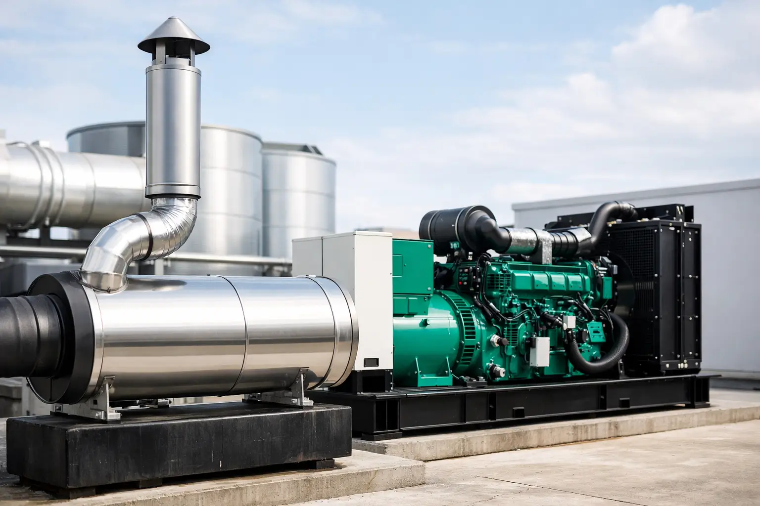
A generator can have the correct kVA rating, a proven engine and a suitable control system, yet still fail to deliver dependable power if its exhaust installation is poorly specified. This generator exhaust system design guide focuses on the decisions that protect engine performance, personnel safety and site uptime. For standby and prime power installations alike, the exhaust system must remove hot combustion gases safely without imposing excessive resistance on the engine.
The exhaust arrangement is not an accessory to be resolved after the generator arrives on site. It is an engineered part of the installation. Pipe diameter, route length, bends, silencing, insulation, drainage and termination point all affect back pressure, noise and long-term reliability.
Start with the engine manufacturer's limits
Every exhaust design begins with the engine data sheet. The most important figure is maximum allowable exhaust back pressure, normally stated in kPa, mbar or mm water gauge. This is the total resistance permitted between the engine exhaust outlet and atmosphere at the applicable rated load.
Back pressure is created by every part of the system: pipework, bends, flexible sections, silencers, rain caps, spark arrestors and any treatment equipment. A design that appears acceptable when measured simply by pipe length can still exceed the engine limit because of restrictive fittings or an undersized silencer.
Excessive back pressure reduces the engine's ability to expel exhaust gases. The practical effects can include higher exhaust temperatures, reduced available power, increased fuel consumption, poor load acceptance and premature turbocharger or valve-related issues. On a mission-critical site, these are not minor efficiency losses. They can undermine the generator's capability precisely when it is needed.
For packaged silent generators, the enclosure may incorporate an exhaust silencer and connection arrangement. The external run must still be assessed against the engine's permitted back pressure. For open generators installed inside a plant room, the full exhaust route will usually require site-specific design.
Size the pipework for flow, not convenience
Exhaust pipe diameter should be selected from the engine manufacturer's requirements and verified against the complete route. Matching the engine outlet diameter is not automatically sufficient, particularly where the discharge run is long, contains several direction changes or serves a high-output diesel generator.
Larger pipework generally reduces friction losses, but oversizing without proper support can introduce unnecessary cost, weight and installation complexity. The objective is not the largest possible pipe. It is a correctly calculated system that stays below the allowable back-pressure limit with suitable margin.
Material selection also matters. Mild steel may be appropriate for many conventional installations when correctly protected, while stainless steel may be justified in corrosive environments, exposed locations or applications where condensate and long service life are significant concerns. The design should account for the operating temperature, external environment and required maintenance life rather than selecting material solely on initial purchase price.
Account for bends, silencers and accessories
Each bend adds resistance. Tight-radius elbows are more restrictive than swept bends, and a route with repeated changes of direction can quickly consume the available back-pressure allowance. Keep the run direct where site conditions permit and avoid unnecessary offsets.
Silencers also require careful selection. A residential-adjacent site, hospital, telecoms facility or urban commercial development may need a higher level of attenuation than an isolated industrial compound. However, a more heavily attenuated silencer can create greater pressure loss. Noise performance and engine breathing must be designed together, not treated as separate problems.
Where a spark arrestor, catalytic treatment system or specialist exhaust equipment is required, include its stated pressure loss in the calculation. Do not assume that optional equipment has negligible effect on the final system.
Route exhaust gases safely from the building and site
The discharge location must prevent exhaust gases from re-entering occupied spaces or affecting air intakes. Exhaust contains carbon monoxide and other combustion products, so termination point selection is a safety-critical decision. Position outlets away from doors, windows, ventilation louvres, roof plant air intakes and neighbouring properties.
A vertical discharge is often preferred because it encourages gases to disperse above the local working area. It is not always the best answer, however. Building height, prevailing wind, planning restrictions, adjacent structures and maintenance access all influence the final route. In complex sites, assess the wider air movement around the building rather than relying only on a simple separation distance.
The outlet should be arranged to prevent rain ingress while avoiding a restrictive cap or terminal. Any weathering component must be included in the back-pressure calculation. Ensure the final arrangement cannot direct hot gases towards combustible surfaces, cable routes, stored materials or public access areas.
For indoor generator rooms, coordinate exhaust routing with combustion air and radiator cooling airflow. A generator installation needs enough fresh air for the engine and an effective route for rejecting radiator heat. Poor coordination can lead to high room temperatures, reduced generator output and difficult maintenance conditions even when the exhaust pipe itself is correctly sized.
Manage heat, movement and condensate
Diesel exhaust pipework operates at high temperatures. Uninsulated sections can create burn hazards, raise plant-room temperatures and pose a fire risk where clearances are inadequate. Use suitable thermal insulation or guards where personnel may come into contact with the system, and maintain safe separation from combustible materials.
The exhaust system must also accommodate thermal expansion and engine vibration. A correctly specified flexible bellows section near the engine isolates vibration, but it is not intended to carry the weight of long pipe runs or correct poor alignment. Support the fixed pipework independently at suitable intervals. Hangers, brackets and expansion provisions must allow controlled movement as the system heats and cools.
Condensate requires equal attention. Exhaust gases cool as they travel through pipework, particularly during short generator runs or in cold external conditions. Where the route allows water to collect, corrosion and flow restriction can follow. Design the system with suitable fall, low-point drainage and accessible drain arrangements. Prevent any collected liquid from flowing back towards the engine.
Specify noise control to suit the operating environment
Generator noise is a combined issue. The engine exhaust is one source, but fan noise, mechanical noise and enclosure breakout noise also contribute. A high-performance exhaust silencer will not compensate for an unsuitable enclosure, poor acoustic treatment or a poorly controlled air intake and discharge path.
Select the silencer grade against the measured or required noise limit at the relevant site boundary or receptor location. The right approach to reduce generator noise depends on the site, operating conditions and required acoustic performance. Typical categories include industrial, residential and critical attenuation, but these labels alone are not a guarantee of compliance. Obtain octave-band performance data where acoustic requirements are demanding, especially where low-frequency diesel engine noise may affect nearby buildings.
The installation layout can influence acoustic performance. Long unsupported runs may transmit vibration into building steelwork, while poorly sealed wall penetrations can allow noise and fumes to pass into adjacent areas. Use appropriate isolation, sealing and fire-stopping measures at penetrations, with materials suitable for the temperatures involved.
Design for access, inspection and commissioning
An exhaust system that cannot be safely inspected is difficult to maintain and harder to trust. Provide access to flexible connections, drain points, supports, silencer bodies and any emissions-control components. Consider how sections will be removed or replaced without dismantling unrelated building services.
Before handover, inspect the complete installation for alignment, support spacing, joint integrity, insulation condition and safe clearances. Confirm that rain protection and drainage are functional, and verify that no temporary caps, packing materials or construction debris remain in the system.
Commissioning should include generator operation under meaningful load, not just an unloaded start test. Measure exhaust back pressure at the designated engine test point and compare the result with the manufacturer's maximum permitted value. Check for exhaust leaks, abnormal vibration, excessive surface temperatures and signs of fumes entering the generator room or nearby occupied areas.
For sites with a standby generator, repeat checks during routine load-bank testing and planned maintenance. Changes to roof plant, ventilation systems, adjacent buildings or the exhaust route can alter how gases disperse and how the installation performs.
Match the exhaust design to the generator duty
A standby generator that runs for short, periodic tests presents different thermal and condensate behaviour from a prime power unit operating for extended periods. Likewise, a 40 kVA generator serving a small commercial site has a materially different exhaust requirement from a multi-megawatt installation supporting a data, manufacturing or infrastructure operation.
The generator rating, engine model, enclosure type, duty cycle, plant-room layout and acoustic target should be considered as one specification. Global Generators can support this process by matching the generator set configuration and power rating to the installation requirement, allowing the exhaust design to be developed from accurate engine and package data.
Treat the exhaust route as critical plant infrastructure. A calculated, accessible and properly commissioned system gives the engine room to perform, keeps exhaust gases where they belong and supports the dependable power supply your operation requires.