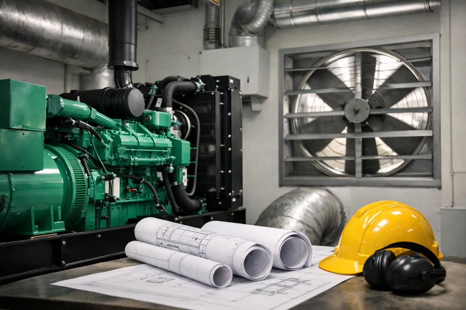
Quick answer: Generator room ventilation must supply enough air for both radiator cooling and combustion, then remove it along a short, direct path with minimal resistance. Start from the manufacturer's heat balance data (not the kVA rating alone), size intake and discharge louvres using certified free area rather than face size, keep the airflow route in a straight line from intake to radiator to outlet, and commission the system under real load — not just a visual check. Get any one of these wrong and the set can overheat, derate, or shut down under load even if it's correctly specified electrically.
A generator can have the correct kVA rating, a proven engine and a properly specified fuel system, yet still fail under load if the room cannot remove heat. Knowing how to plan generator room ventilation is therefore a core part of standby and prime power design, not a finishing detail for the building contractor. The objective is simple: supply enough clean combustion and cooling air, remove radiator discharge heat efficiently, and maintain safe operating temperatures in every expected condition.
For critical sites, ventilation design should begin alongside generator selection. Retrofitting louvres, ductwork or extraction after installation is usually more expensive and can introduce restrictions that compromise output, service access or acoustic performance.
Start with the generator heat balance
The first input is the generator manufacturer's technical data. Do not estimate airflow from the electrical output alone. Two diesel generators with a similar standby rating can have materially different radiator airflows, combustion-air demands and allowable external static pressure.
Obtain the selected set's data for radiator cooling-air volume, combustion-air volume, radiator fan static-pressure capability, exhaust heat rejection, alternator cooling requirements and maximum permitted ambient temperature. For an enclosed room, the radiator airflow is normally the dominant figure. Combustion airflow is smaller but remains essential, particularly where air is ducted or the set operates at high load for extended periods.
The design must also account for heat entering the room from the engine block, alternator, exhaust pipework, control panel, chargers and associated equipment. In a conventional arrangement, the engine-driven radiator fan draws air through an intake louvre, across the generator package and radiator, then discharges it directly outdoors. This is generally the most efficient approach because it removes the largest heat source without allowing it to circulate around the room.
Ambient conditions matter. A set rated at a stated ambient temperature may need derating or additional cooling where the site experiences high summer temperatures, solar gain, plant-room heat from adjoining equipment, altitude effects or dirty external air. Standby systems should be assessed at their required load profile, while prime-power applications need particular care because heat exposure is sustained rather than occasional. Sustained low-load or poorly ventilated running can also contribute to wet stacking, so airflow and load profile should be reviewed together rather than in isolation.
Set the airflow route before sizing louvres
Good generator-room ventilation follows a clear, low-resistance path. Cool air enters near the engine alternator end, travels through the room and generator, then leaves at the radiator end. The discharge route should be as short and straight as practicable.
Position the intake louvre so that incoming air does not immediately short-circuit to the outlet. It should also be placed away from hot discharge air, boiler flues, vehicle exhaust, cooling-tower drift and areas where dust, leaves or water can be drawn in. Where a building façade forces the intake and discharge onto the same elevation, separation and careful louvre orientation are required to prevent recirculation.
At the outlet, the radiator should connect to a correctly designed discharge plenum or duct. The interface between radiator and duct must be sealed with a flexible connection that accommodates vibration and avoids imposing generator weight on the ductwork. Gaps around this connection are a common cause of hot air bypassing back into the room.
Ducting is sometimes unavoidable, particularly for basement installations or acoustic enclosures. It is not free. Every bend, transition, louvre, bird guard and silencer adds pressure loss. If total resistance exceeds the radiator fan's available external static pressure, airflow falls and coolant temperature rises. This can cause high-temperature alarms, load rejection or premature engine wear.
Use free area, not louvre opening size
A louvre's overall face size is not its usable airflow area. Blades, frames, weather protection, mesh and acoustic treatment reduce the free area substantially. Specify louvres by certified free area and pressure-drop performance at the actual design airflow.
A louvre that appears generous on a drawing may be too restrictive once a rain louvre, insect mesh and acoustic attenuator are included. Fine mesh is especially problematic in dusty industrial environments because it quickly blocks. Where filtering is necessary, ensure it is accessible for inspection and include maintenance intervals in the operating plan.
Size intake and discharge for real resistance
Vent openings and ducts must be sized from the required airflow and the pressure losses the system can tolerate. The generator data sheet identifies fan capability, but the complete system calculation should include intake louvres, grilles, duct lengths, bends, transitions, flexible connections, silencers and discharge louvres.
Large, low-velocity openings usually provide better results than compact, high-velocity solutions. Lower air velocity reduces pressure drop, noise and rain entrainment, while allowing more margin as louvres become dirty. It can, however, increase the façade area required and may affect security or architectural constraints. These are project decisions, not reasons to reduce airflow capacity.
Where the room contains more than one generator, consider each operating scenario. A system may run one set at a time, two in parallel, or all units during a utility failure. Ventilation must support the maximum credible simultaneous duty, including any future expansion identified in the project brief. This is particularly relevant for data centre installations, where redundant sets may need to run together during extended outages. Do not assume that all radiator fans will share a common outlet without checking interactions and backflow risk.
Motorised louvres can reduce heat loss, dust ingress and wind-driven rain when the generator is stopped. They must fail to a safe operating position and open before or as part of the generator start sequence. Their opening time, end-switch feedback and cold-weather reliability should be tested. A closed or partially opened outlet louvre can rapidly create an over-temperature event.
Manage exhaust, combustion air and room pressure
Radiator discharge air is not the same as engine exhaust. Exhaust gases must be carried outdoors through rated exhaust pipework, with correctly designed silencers, expansion sections, insulation and supports. Exhaust termination must prevent gases entering ventilation intakes, occupied areas or adjacent plant rooms.
The engine also needs clean combustion air. In most installations it is drawn from the generator room, so the ventilation intake provides both cooling and combustion air. In heavily contaminated areas, coastal sites, tunnels or process facilities, the air quality may require filtration, corrosion-resistant components or a more specialised arrangement.
Avoid excessive negative pressure in the room. Extraction fans, smoke-control systems or adjacent mechanical ventilation can oppose radiator fan flow and reduce available combustion air. Similarly, a pressurised room can disrupt the intended cooling path. Coordinate the generator design with the building ventilation strategy, including fire-mode operation and any automatic dampers.
Consider fire, noise and weather as design constraints
A generator room is not simply an air path. It is also a fire compartment, an acoustic enclosure and a weather-exposed part of the building. The ventilation design must meet the applicable building, fire, environmental and planning requirements for the project location.
Fire dampers are not automatically suitable in a generator radiator discharge path. A standard damper may add unacceptable resistance or close when the generator must continue supplying life-safety loads. The required approach depends on the building fire strategy, fuel arrangement, generator duty and local authority requirements and should be checked against Building Regulations Approved Document B (Fire Safety).This needs early agreement between the generator supplier, mechanical designer and fire engineer.
Noise control also creates trade-offs. Acoustic louvres and attenuators can be necessary where plant rooms are close to offices, homes or hospital spaces, but they add resistance. Select them from tested acoustic and aerodynamic data, not only a quoted sound reduction. A quieter louvre that overheats the generator is not a successful solution.
Weather protection needs the same discipline. Louvres must resist rain ingress without choking airflow, and discharge points should not allow wind to force hot air back through the radiator. In cold locations, consider frost, snow loading and the need to maintain suitable room temperature for starting batteries, fuel systems and control equipment.
Build access and maintenance into the layout
Ventilation performance changes over time. Leaves collect on external grilles, filters load with dust, flexible seals degrade and accidental alterations are made to ductwork. Provide safe access to both intake and discharge components without requiring major isolation works or working at height without suitable arrangements.
Keep the room layout clear around the generator. Air should not be obstructed by fuel tanks, cable trays, stored materials or later-installed equipment. Service clearances specified by the generator manufacturer remain essential, particularly around radiator cores, air filters, control panels and exhaust components.
Temperature monitoring gives useful operational assurance. Room temperature, coolant temperature, louvre position and fan status can be brought into a building management system or remote monitoring platform. Alarms should distinguish between a genuine cooling fault and a sensor issue, and should be tested during loaded generator operation.
Commission ventilation under load
A visual inspection is not commissioning. The generator should be tested at an appropriate load while engineers confirm room and coolant temperatures, airflow direction, louvre operation, fan performance and the absence of hot-air recirculation. Thermal imaging and smoke testing can reveal leaks around radiator plenums or unexpected short-circuit paths.Our guide to generator load bank testing explains how to structure this kind of test properly.
Test in realistic conditions where possible. A set that runs satisfactorily for ten minutes on a light load may overheat after a prolonged load-bank test, especially when outside temperatures are high. Record the ambient temperature, load level, run duration and all temperature readings so there is a usable baseline for future maintenance.
For new installations, the most dependable route is to select the generator, room layout, louvres and ducting as one engineered package. Global Generators can support early equipment selection with clear generator data, helping project teams match the ventilation strategy to the required standby or prime power duty before the room is built. A well-designed air path is quiet in operation, easy to maintain and rarely noticed - exactly how critical power infrastructure should perform.