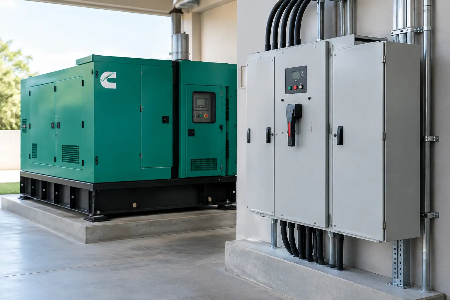
A generator can be correctly sized, fuelled and maintained, yet still fail to protect a site if the changeover arrangement is wrong. Automatic transfer switches are the control point between utility supply, standby generation and the load. Their job is to detect an unacceptable mains condition, start the generator, transfer the load when generator power is stable, and return the installation to the preferred source when normal supply is restored.
For facilities where loss of power affects production, safety systems, refrigerated stock, communications or public services, this sequence cannot be treated as an afterthought. The transfer switch must be specified alongside the generator, distribution board, load profile and operating priorities.
What an automatic transfer switch does
An automatic transfer switch, often abbreviated to ATS, monitors the incoming mains supply for failure or conditions outside acceptable voltage and frequency limits. When those limits are breached for a programmed period, it sends a remote start signal to the generator. Once the generator reaches the required voltage and frequency, the ATS disconnects the load from the mains and connects it to generator power.
When the mains supply returns and remains stable through the programmed retransfer delay, the process reverses. The load is transferred back to utility power, and the generator completes a cool-down period before stopping.
The fundamental requirement is break-before-make operation. The load must not be connected to both sources at the same time unless the installation has been specifically designed for closed-transition switching and utility approval has been obtained. A properly specified ATS prevents back-feeding into the network and protects personnel, plant and generating equipment.
Transfer time matters, but it is only one part of the requirement. Most standard standby generator systems have an interruption while the engine starts and stabilises. That is acceptable for many applications, including warehouses, offices, construction compounds and general industrial loads. Equipment that cannot tolerate even a short interruption may require an uninterruptible power supply, battery-backed controls or another ride-through solution ahead of the generator system.
Selecting automatic transfer switches by application
The switch rating must reflect the electrical system, not simply the generator nameplate. Start with the site voltage, phase arrangement, frequency and maximum continuous load current. In the UK, this will commonly mean a 400/230 V, three-phase, 50 Hz installation, but generator sets and switchgear supplied for export may require different voltage and frequency configurations.
A three-phase generator supplying a mixed commercial or industrial load normally requires a four-pole ATS where the neutral needs to be switched. Whether a three-pole or four-pole arrangement is appropriate depends on the earthing system, generator neutral-earth bonding arrangement and wider distribution design. This is a design decision for a competent electrical engineer, not a detail to be assumed from the generator size alone.
The rated current must also allow for the actual duty of the installation. Motor starting, transformer energisation, welders, compressors, pumps and other inductive loads can create significant inrush. A switch that appears adequate under steady-state conditions may be unsuitable if its making, breaking or short-circuit withstand capability does not match the site fault level and load characteristics.
Standby power versus prime power
For a standby generator, the ATS is generally configured to operate only when the mains source is unavailable or unacceptable. The priorities are dependable fault detection, safe transfer and controlled retransfer.
For prime power applications, the operating logic may be more involved. A site may use generator power for extended periods, transfer between generator sources, or operate with mains as a secondary supply. In these cases, switching equipment, protection settings and fuel autonomy should be considered as one engineered package. The ATS may need additional metering, remote communications, load-shedding outputs and control integration.
Open transition, closed transition and bypass isolation
Most generator installations use open-transition transfer. The ATS breaks the connection to one source before making connection to the other. It is proven, cost-effective and suitable for the majority of standby applications. The trade-off is a brief interruption during each transfer.
Closed-transition transfer briefly parallels the mains and generator during retransfer, reducing or eliminating the interruption to the load. It is useful where even a short break is commercially disruptive, but it adds cost, commissioning complexity and protection requirements. It also depends on the local supply authority and the site’s connection agreement. It should not be selected simply because it sounds more advanced.
Bypass-isolation ATS equipment is worth considering on high-consequence sites. It allows the transfer switch to be isolated and maintained while the load remains supplied through a manual bypass arrangement. Hospitals, data environments, transport infrastructure and continuous-process facilities may benefit from this maintainability, provided staff procedures and switchboard design support safe operation.
Control settings that affect uptime
A quality transfer switch is only as effective as its settings. Poorly chosen delays can cause nuisance generator starts, unnecessary transfers or an avoidable return to mains before the network is stable.
Key parameters typically include mains failure delay, generator start delay, voltage and frequency acceptance limits, transfer delay, retransfer delay and generator cool-down time. A brief voltage dip should not necessarily start a generator. Equally, a critical facility should not wait through a long delay before the generator receives its start command.
Retransfer deserves particular care. Utility power may return briefly after a wider fault, then fail again. A sensible retransfer delay confirms that the mains is genuinely stable before reconnecting critical loads. The correct setting depends on the supply quality, process sensitivity and generator duty cycle.
Load shedding is another valuable function where generator capacity is finite. The ATS or generator controller can prioritise essential circuits and shed non-critical loads such as comfort cooling, selected process equipment or vehicle chargers. This can avoid overload trips during an outage and allows a generator to be specified around genuine critical demand rather than total connected load.
The generator and ATS must be specified together
A generator rated at the required kVA is not automatically compatible with every transfer arrangement. The alternator, engine governor, controller, breaker rating, starting method and load profile all influence how the system performs after a transfer.
For example, several large motors starting together after generator connection can cause a voltage dip that drops contactors or prevents machinery restarting. The solution may be staged restart logic, variable-speed drives, soft starters, a larger alternator, or a larger generator set. The ATS can provide programmable outputs to bring loads back in sequence, but the strategy must be agreed before installation.
Physical configuration matters too. A silent generator can be installed close to occupied or noise-sensitive areas, while an open generator may suit a plant room or protected enclosure. The ATS itself needs an accessible, dry location with appropriate cable routes, clear labelling and safe isolation provisions. Long control cable runs, remote fuel systems and fire interfaces should be included in the project scope rather than dealt with on site as variations.
Global Generators can support this process by matching generator output, control capability and enclosure format to the intended standby or prime power application.
Installation, testing and maintenance
ATS commissioning should prove the entire operating sequence under load. A no-load generator run is not enough. Testing should confirm mains sensing, start signal operation, source transfer, voltage and frequency stability, load acceptance, alarms, retransfer and cool-down. Any emergency-stop circuit, fire shutdown, remote monitoring system and interlock must also be verified.
Maintenance requirements vary by switch type and duty, but the principles are consistent: inspect connections for heat damage or looseness, check control wiring and batteries, review event logs, exercise the generator and carry out planned transfer tests. Where operational risk allows, periodic load testing provides much more useful assurance than simply observing an engine start.
Document the final settings, single-line diagram and operating procedure. These records matter during call-outs, statutory inspections, generator replacement and after changes to the building load. They also help prevent a well-intentioned settings adjustment from creating a reliability issue.
Common specification errors to avoid
The most expensive ATS problems usually begin before procurement. Avoid selecting a switch solely on amp rating, assuming all neutrals should be treated the same, or overlooking the available short-circuit current at the switchboard. Do not specify an ATS without considering how the generator will receive its start signal, how essential loads will restart and whether the building has a UPS or fire-system interface.
It is also unwise to treat automatic transfer as a substitute for generator maintenance. The switch can issue a start command, but it cannot overcome contaminated fuel, a weak starting battery, blocked filters or an engine fault. Uptime comes from a maintained system with correctly coordinated components.
For a live site, the best starting point is a clear load schedule, the existing electrical single-line diagram, generator duty requirement and an honest definition of which circuits must remain operational. With those details established, the transfer arrangement can be engineered to support the operation rather than becoming its weakest point.